I have been playing around with SigmaStudio quite a bit by now. Some is quite intuitive and some is not. I had to learn most the hard way browsing through the online documentation and the EngineerZone support forum. There you will find tons of information but I could not find a straight forward tutorial to get me up and running with a preamp or active crossover project. There are bits and pieces but I could not find anything holistic connecting the dots. I will therefor sum up my experiences in a series of tutorial style blog posts. The focus will be on getting started with SigmaStudio and to build a preamp project including active crossover and a Linkwitz Transform. I will use SigmaStudio version 4.6 and the ADAU1701 based DSP from 3e Audio. I will initially focus on utilising the analog two channels input and four channels output.
Start SigmaStudio, create a new project, add a ADAU1701 and an E2Prom block from the Processors (ICs / DSPs) ToolBox. Next add a USBi block from the Communication Channels ToolBox. Connect the ADAU1701 and E2Prom blocks to the USBi block. The Hardware Configuration tab (Config section) of your project should now look like this:
The USBi header will be green if SigmaStudio is actually connected to the DSP through the DSPi interface. It will be red if there is no contact. This tutorial assumes you got a working USBi interface.
There are two additional sections in the Hardware Configuration tab, one named IC 1 - 170x/140x Register Control and one named IC 2 - WinEpromLoader. Switch to the register control section:

Its a lot but not too hard to get. What you see is a representation of the DSP hardware. Press the top left button named Read All. It will read the current state of your DSP hardware (check the Capture window). Check the GPIO block, here you got all settings regarding GPIO pins. Make sure the checkbox named Enable in the Control ADC section is checked if you are going to use the onboard auxillary ADCs (e.g. a potentiometer for volume control etc.). Keep as much as possible default if you don't know what these settings are doing. Also make sure the System Sampling Rate is set to 48 kHz in the dropdown list, top middle on the SigmaStudio main toolbar. You might think higher sample rate is better right? It can be but there is a trade-off with a DSP. There is a finite amount of available instructions per sample. The amount is related to the system sample rate. You get less available instructions the higher you set the sample rate. Therefor start out at 48 kHz and see just how many instructions your project will need before you crank up the system sample rate.
Now switch to the Schematics tab and add one Input and four Output blocks from the IO ToolBox. Next add two T Connection blocks from the Systems ToolBox. Connect Input 0 to the first T Connection and Input 1 to the second. Connect Output 1 and 2 to the first T Connection block and Output 3 and 4 to the second T Connection block. Your project should now look like this:
This is now the perfect project to check that everything is working as it should. Start by linking the project (use the menu button or menu Action -> Link Project). Check the Errors / Output window, you should have no errors.
WARNING: The DSP can make noises when programmed, memory can get corrupt or input to a block might be "wrong". The result might damage your speakers if the DSP is hocked up to an amplifier with speakers attached. I therefor recommend that you connect the outputs to some cheap PC speakers. Mine got volume control and headphone outs where I connect a couple of really cheap headphones. Use this test rig while programming and experimenting with the DSP. Only hook it up to some serious gear when you verified your project, after a successful flash to EPROM and reboot. Make sure you mute the amplifier if you ever decide to program and flash the DSP while connected to anything you care about.
With your test rig in place, time to Link, Compile and Download the project to the DSP (use the menu button or menu Action -> Link Compile Download).
The blue bar above the Capture window in the previous screenshot should go green as in this screenshot. The status readout, down right, should also be green and read Active: Downloaded. You project is now compiled and downloaded into the DSP. You can now test the input and outputs. Any input signal on Input 0 should now playback on Output 1 and 2. And any input signal on Input 1 should playback on Output 3 and 4.
This code is currently in volatile memory and it will be gone as soon as the DSP is powered off. We therefor need to store it permanently in EPROM in order to enable the DSP to load it at boot-up. Switch back to the Hardware Configuration tab, Config section. Right-click the ADAU1701 block and select Write Latest Compilation to E2PROM. Press OK in the next dialog and watch the progress bar while the code is stored in EPROM. You should now be able to power cycle the DSP and it should boot-up loading the latest project you written to memory.
You now have a verified toolchain and the basic knowledge to start a new project, connect input to output, compile and download code to the DSP and to store it in permanent memory so that it is loaded at boot-up.
The best way to learn more about SigmaStudio and the DSP is to experiment. You don't have to use an analog input source or amplification and speakers at the outputs to do a lot of experimentation. Switch to the Schematics tab (save your current project if you want) and clear the project.
Add a Sine Tone block from the Sources ToolBox. Enter 1000 in the frequency field. Add a Single Volume block from the Volume Controls ToolBox. Add a Single Level Detector w Numeric Display block from the Level Detectors/Lookup Tables ToolBox. Connect the Sine Tone block to the Single Volume block. Connect the Single Volume block to the Single Level Detector. Your project should now look like this:
Link, Compile and Download the project to the DSP (use the menu button or menu Action -> Link Compile Download). Enable the Sine Tone block (check the on / off checkbox) and enable the Level Detector block (flip the GUI switch to on). The Level Detector should now read -3 dB because it is the RMS value of the 1 kHz sine tone generated at 0 dBFS. Change the slider of the Single Volume block (or right click it and enter a new dB value) and see how the level changes in real time. Lets take this one step further.
Insert a Gain block from the Basic DSP ToolBox between the Sine Tone and the Single Volume. Click Lin to change it to dB, enter 9 dB as a new gain value. Add a T Connection block from the Systems ToolBox and a Mono Switch Nx1 from the Muxes/Demuxes ToolBox. Right-click the Mono Switch -> Add Algorithm -> IC 1 -> Mono. Add a Standard RMS (Compressor) from the Dynamics Processors ToolBox. Right-click it -> Add Algorithm -> IC 1 -> Standard Stereo RMS Second Gen. Connect the Single Volume to the Single Volume, the Single Volume to the Standard RMS (Compressor), the Compressor to the Mono Switch and the Switch to the Level Detector. Open up the Compressor by clicking on the button (on its centre). Enable Level Indicators (by flipping the GUI switch). Link, Compile and Download the project to the DSP (use the menu button or menu Action -> Link Compile Download). Your project should now look like this:

Play around with the controls to learn more about how the Compressor works. Lets finish this post with another way of experimentation. Save your current project if you want then clear the project.
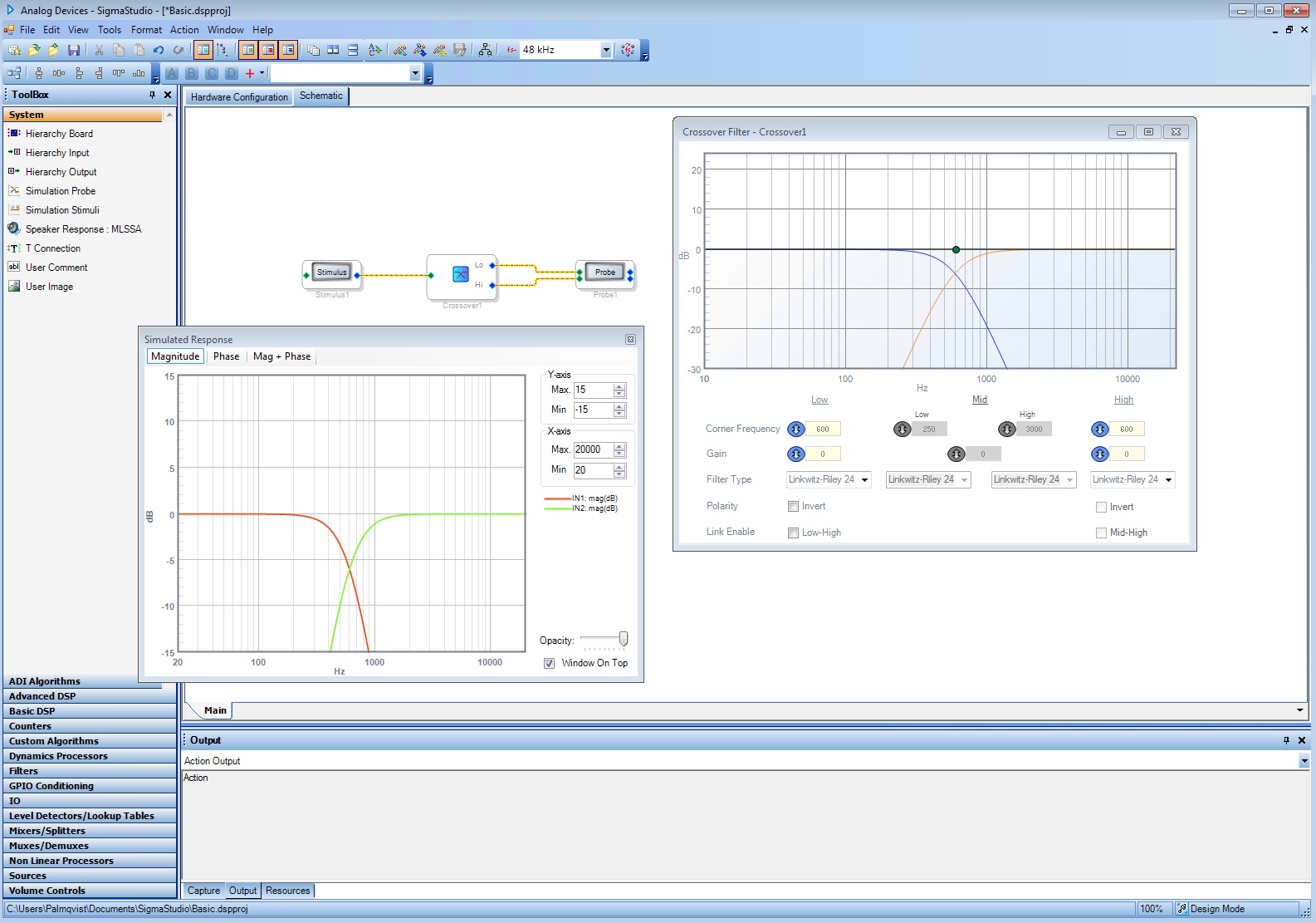
Add a Simulation Stimuli and Probe block from the System ToolBox. Right-click the Probe -> Add Pins. Add a Crossover block from the Filters ToolBox. Right-click it -> Add Algorithm -> IC 1 -> 2-Way Crossover Filter - Double Precision. Connect the Stimuli to the Crossover and the Crossover to the Probe. Open up the Crossover Filter and Probe by clicking on the button (on its centre). Enter crossover frequencies and press the Stimulus button on the Stimuli block. Your project should now look something like this:
Note: The stimulus/probe cells only work with linear, time-domain processing blocks. The Probe will not work if a transform (for example, the Hilbert transform) is placed between it and the Stimulus. Examples of valid and invalid block combinations for Stimulus/Probe are on this page.
You should now know the very basics to get you going with SigmaStudio and to start experimenting with your DSP. More advanced and complex topics and examples to follow, stay tuned...