Ortho Acoustic WAW Part 2.

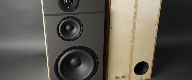
I will approach this build piece by piece and start with the concrete box. I might have to rethink the concrete part if it turns out too heavy or non functional in some other way. I am aiming for something similar in size and shape as the OA-50. I have no drawings but the official specifications states: W x H x D: 38.8 x 46.6 x 31.6 cm. I know I need 15 liters for the sub and 6-8 liters for the W5-2143.
I started out making a spreadsheet calculating inner volume, concrete volume and weight based on outer dimensions and wall thickness. I ended up with a box with the outer proportions of W x H x D: 42 x 23 x 32 cm. It equals some 20 liters inner volume with a wall thickness of 2 cm. The amount of concrete needed is a bit less than 10 liters if I make it as a box without a top. The weight will then be a bit less than 20 kg.
I was initially designing a box with a cutout for the plate amps. But it weakens the box quite a bit and I might want to drive these speakers with something else in the future. I will therefor design for external amplifiers adding just a Neutrik speakON NL4MP 4 pole chassis connector to the box.
The best material to make a form out of is probably some concrete forming plywood, especially if you are going to use the form to make more than one speaker. The only drawback is that it is quite expensive compared to melamine covered chipboard. I went the cheap route but I kind of regret it. The chipboard is fragile and a pain to work with and I probably have to make two sets of forms, one for each speaker box.
This is what the outer box looks like. Making forms forces you to think backwards, in negative space. The inner dimensions of this box is 42 x 32 x 23 cm (W x D x H). The inner box will be fixated to this box with the help of a couple of screws from the bottom and two wooden dowels making sure it is positioned in the center. All inner edges has been sealed with black silicone caulk (black because it is easier to spot it against the white melamine).

The bottom of the inner box (that will become the top) is a bit wider to form a rabbet where the baffle will be mounted. The sides are screwed to the bottom but the rest is kept in place with duct tape. A handle has been screwed to the inside of the top (that will be the bottom). It will hopefully make it possible to pull it out of the concrete when the sides has been removed.

I also need to make a "hole" for the chassis connector. Luckily Neutrik provide CAD drawings of their products on their webpage so it was fairly easy to make a 3D plug that I could print out with the 3D printer. I made it 1 mm oversized and added a 6 mm peg on one side to fasten it to the inner box (to fasten it I just drilled a 6 mm hole in the box and inserted the peg into it).

I played around with different kind of reinforcements but I ended up using two layers of chicken wire. I wanted to make sure any reinforcement was at least 5 mm from all visible surfaces and it was hard with more traditional reinforcements. The chicken wire was easy to shape and I could use some additional wire to sew it together. Not optimal as reinforcement maybe but hopefully good enough.

This is a detailed picture of the 3D printed chassis connector plug sitting in between the outer and the inner form. I don't know exactly how to get it out of the concrete but I should be able to drill it out or heat it up with a hot gun or something I guess...

And this is a picture from up above. Next step is to mix some concrete and pour it into the form (the void between the two boxes are 2 cm wide)...