The 3-Way Retro Part 6.

These changes freed up quite some real estate, hopefully enough to be able to fit another SMPS600RS (48V for the TPA3255). These switch mode power supplies got 12V AUX-power but it is regulated and does not collapse fast enough to drive a simple thump eliminating circuit like the one I use to use. It is simple and usually works but the ones interesting in solid speaker protection should read up on Rod Elliott's material on this subject, like:
- P33 - Loudspeaker Protection and Muting
- P111 - PIC Based Speaker Protection
- P120 - Crowbar Speaker Protection
- P175 - Single Supply BTL Amplifier Speaker Protection
- P208 - Amplifier Powered DC Protection Circuit
The speaker protection boards I had been using in my PwrFUNK build was quite large so it would be nice to be able to replace them with something else. My first thought was to use the DSP since the ADAU1701-2In4Out from 3e Audio comes with a pin header - AMP Reset IO (J1&J20) and the TPA3251 and TPA3255 boards got similar pin headers - Control Signal Connector (J5). These boards will be muted if pin 4 RESET is grounded (like connected to pin 1 GND). The AMP Reset IO on the DSP is driven by GPIO so it should be quite straight forward right?
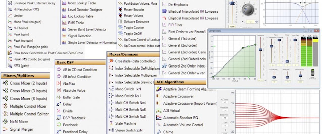
But the "Auto Mute" Hierarchy Board in the SigmaStudio project from 3e Audio is password protected if you remember. Not much of a problem if you use it as pre programmed but what if you want to roll your own project? It is easy to guess that AMP Reset IO (J1&J20) is driven by the same GPIO out as the LED and there is some examples of timers etc. on the Sigma site. I started to put something together like this:

The idea is to activate GPIO_2 (Amp Reset) for 3 seconds on power up and after a couple of seconds if no output signal is detected. This might work (I don't know because I gave up on the idea before I event had the chance to test it) and it might be of use to someone else. What made me hesitate was the fact that GPIO on the DSP float during power up. Pull-down resistors might be used, I haven't tested but what about power down? You would have to stop playback a couple of seconds before you turn the power off. It might work but I wanted a more solid solution tied to the mains power if possible.
The simplest solution would be to go back to the Thump Eliminator circuit, let it drive a relay connecting Normally Closed (NC) to Control Signal Connector (J5) pin 1 and 4. But I would need something to drive the circuit. Luckily a friend of mine donated a PCB transformer he had in his part bin.

Not the perfect voltage or power but it was free. So I put together the following schematics in DipTrace.
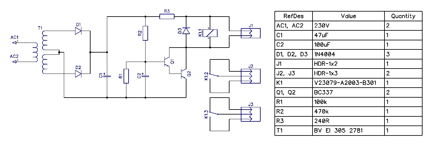
It uses a full wave rectifier instead of a half wave. I will use J1 for a status LED, J2 and J3 will be connected to pin 1 and 4 on the AMP Reset IO (J1&J20).
I then made a PCB and used the 3D printer to print an enclosure for it (note: there is an error in that PCB so don't try to make it as is, follow the schema above instead, it is correct).

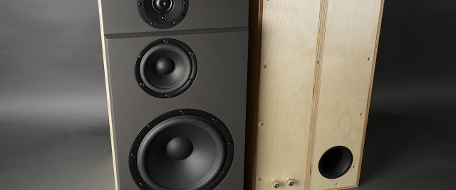
And this is what the final result looks like (to be fed from the mains switch in the PwrFUNK).

This little "Thumpinator" is connected like this:

The R/C-network gives a 3 seconds delay after power on before the relay is activated. The relay will close within a couple of cycles at power off. It is tied to the power button and it normally just works.
I also fitted a NAUSB3-B, a reversible USB 3.0 feed through adapter from Neutrik. I wanted to be able to hookup a computer to the DSP and reprogram it without having to take the cabinet apart. I reversed the NAUSB3-B so that the USB-B side was facing outside. I could then fit the USBi interface I bought with the DSP straight into the USB-A side facing inside (top left in the picture).

I am not a big fan of JST connectors for audio but it is what the boards are fitted with. I used the cables that came with the DSP to hookup the amp boards but I will probably make better ones like the shielded one I made for input from the RCA connectors. The DSP board is powered from one of the amp boards. It is neat but I had to make the power cable my self since it is not delivered with the DSP nor the amp boards.
So the back of the PwrFUNK now sports a USB-B connector for the DSP :)

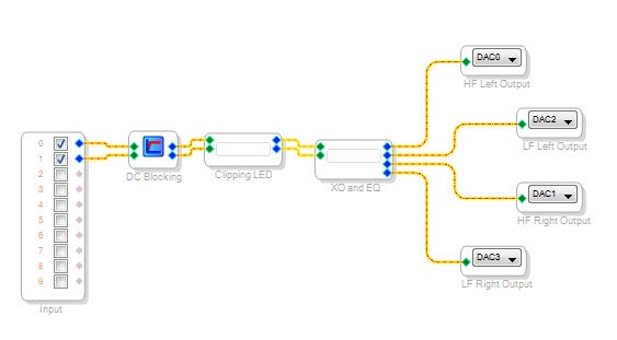
The pin-out between inputs and outputs are now like this.

And I therefor updated the outputs in my SigmaStudio project like this.
The only thing missing before I can finalize this project is the veneer. I ordered it in August but it has not been delivered yet. I will have to put this project on hold until it does...