Modding the NISSEI TR-35 VU Meter Part 2.
I promised a followup with a circuit to drive the NISSEI TR-35. I have built and tested several circuits I found on the Internet and to make a long story short, the best I found was Rod Elliotts P55 (surprise, surprise). It is simple yet elegant and I really like the PPM feature. Rod designed the circuit for an input signal of 500 mVrms and a meter with a sensitivity of 50 or 100 uA and a DCR of 3500 Ohms. I asked myself what needs to be changed in order to make it work with the NISSEI TR-35 (180 uA and 650 Ohms) and an input signal like Consumer Audio Line Level (−10 dB, 0.316 Vrms) to Professional Line Level (+4 dBu, 1.228 Vrms)?
I sent Rod a question and got the answer that the circuit should work with pretty much any meter but that I needed to increase the value of R8 (220 ohms) so the total resistance including meter coil is around 200 Ohms. So 650 + 330 || 218.88 Ohm, pretty close but 300 is even better with || 205.26 Ohms.
I simulated the circuit in TINA-TI with R1 = 10k, R8 = 300R and R7/R9 = 18k. It was looking promising and the trimmer would hopefully cover the whole span of 0.316 to 1.228 Vrms.
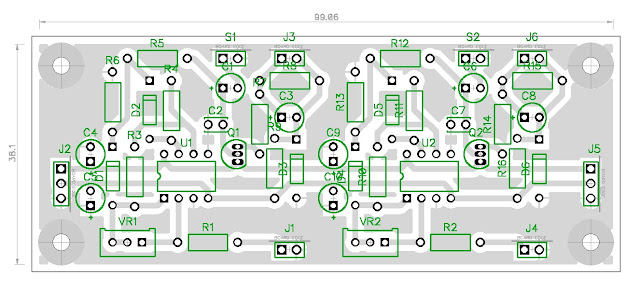
Next step was to put a schema together in DipTrace. I needed two boards to drive four meters so I made the power rails go through the board so they could be daisy chained. I made some changes as can be seen in the BOM. I used TL072 instead of LM1458 and BAT43 Schottky diodes instead of OA91 (or OA95, 1N60, 1N34A etc.) germanium diodes.


