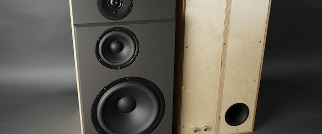
I decided to go with an all metal enclosure this time. I wanted to keep it around 30 cm deep because deeper than that usually put restrictions on placement. I wanted to keep it as low as possible but its not like a power amp where the VU-meters can take up all front panel estate, I need enough height for a volume knob and I don't want to make it small if I got gigantic VU-meter on top of it. I finally decided to order a Pesante 04PB 4U by Hi-Fi 2000 from Modushop.
I ordered it without front panel, not because I don't trust their machining service but mainly because Im not sure what the front panel will look like. I did however order the inner baseplate. It is a super useful addition to the enclosure. The holes are spaced 10 mm apart and it is super convenient to put together both sides, the back panel and the baseplate while mounting all the electronics inside.
I like this enclosure a lot. Great quality and easy to work on. It is great the the back panel can be removed and put flat on the workbench. It makes it super easy to drill holes or whatever machining that needs to be done. Here is a trick if you don't have access to a CNC-machine or drill press. I use a CAD program to layout the holes to be drilled. I then 3D-print jigs that I fasten with some double sided tape and a clamp while drilling the holes on low speed with a cordless screwdriver. The jig will keep the drill bit straight and keep it from wandering.
 |
|
I did not choose the option with the IEC socket because I wanted to use a C14 socket with built in fuse. It can here be seen with the safety ground fastened to the inner baseplate. Make sure every other piece of the enclosure got good contact with the base plate. The black anti-scratch paint is thick and a grate insulator. Make sure to strip enough paint to make good contact between all panels and the inner baseplate. And use tooth washers where it makes sense.
I use double insulated cables for the mains and splitters like this if I have to distribute to more than one unit.
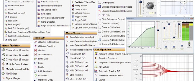
I have been really impressed by the
TPA3255 based amp board and I wanted to try it out with an old school unregulated liniar power supply. Not because I think I would hear the difference to the SMPS I have been using but because of the simplicity in design. It makes it easy to maintain and I already scavenged the transformer from an 80s Sony integrated. I also nicked the power filter components and some other parts for this build.
One annoying thing with the
PwrFUNK has been power on switch "arcing". The Sony amp had a capacitor across the mains terminals so I nicked that one too. I then used the 3D-printer to print ha small enclosure holding a small PCB where I mounted the capacitor close to the power switch.
I added silicon grommets to the large E-core transformer when mounting it to the baseplate. This type of grommets can be scavenged from PC enclosures usually used to mount rotating hard drives.
Power supplies and distribution mounted and tested. It takes up a lot of estate, more than 1/3 of the baseplate.
Mains C14 socket (top left), feeding the E-core transformer and a toroidal transformer (left). The toroidal is shared by two power supplies. One DIY regulated 12V PSU with a R/C-network delayed unregulated output to drive the power on muting (top) and one +15-0-15V PSU (
Rod Elliott P05-Mini) to drive RIAA amp, headphone amp and VU-meter driver board (middle). A junction board that also function as small signal star ground (right). Chassis ground can be seen next to safety ground (top left)
The centre tapped E-core is driving a DIY unregulated full wave rectified PSU delivering 42V without load. It will deliver around 38V under resonable load.
Power done and tested. Next update will be about the rest of the electronics inside.
Ps. The naked primary and secondary poles on the transformer will get some sort of 3D-printed covers for safety, just not done yet. :)