This post will be about level matching and why it is important. It might be the single most important aspect to get right because if you don't, it will sound awful and you might not even understand why.
A DSP is just like any other piece of equipment in your sound chain. It will probably have a piece of equipment before it and another after it. The signal level between these components must be matched to get the best possible sound quality through this sound chain.
The first thing that has to be fully understod is found on page 29 in the ADAU1701 Data Sheet, it reads:
The serial port accepts up to 24 bits on the input and is sign-extended to the full 28 bits of the DSP core. This allows internal gains of up to 24 dB without internal clipping. A digital clipper circuit is used between the output of the DSP core and the DACs or serial port outputs (see Figure 29). This clips the top four bits of the signal to produce a 24-bit output with a range of 1.0 (minus 1 LSB) to −1.0. Figure 29 shows the maximum signal levels at each point in the data flow in both binary and decibel levels.
Lets break this down a bit. There is a 24 dB headroom in the DSP core so you may apply up to 24 dB in the core from 0 dBFS without clipping. But anything above 0 dBFS leaving the core will be clipped on the outputs. So you will have to attenuate anything above 0 dBFS down to 0 dBFS or below before it leaves the core to prevent it from being clipped. That is the digital domain but what about the analog domain?
The analog input is just like any amplifier, it has an input impedance and a sensitivity. If the signal you feed to it is too strong it will be clipped on the inputs. Why is clipping bad? The task of an audio amplifier is to take a small signal and make it bigger without making any other changes to it.
A common type of amplifier distortion is called harmonic distortion. It can arise if any component in the amplifer clips the peaks of the waveform.
In the diagram, the input is a single frequency (pure sine wave), but the output waveform is clipped by the amplifier. The result is that harmonic frequencies not present in the original signal are produced at the output (harmonic distortion). This is bad, right?
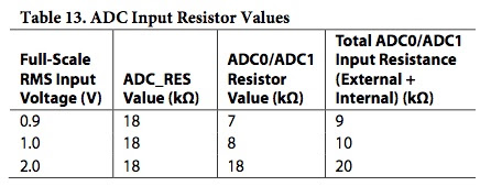
When will the analog inputs start to clip? T
he full scale RMS input voltage is given by Table 13 on page 20 of the ADAU1701 Data Sheet.
The
DSP from 3e Audio is configured for an input sensitivity of 1.1 Vrms (i.e. 8.2 kΩ ADC0/ADC1 resistors). So for this DSP 1.1 Vrms on the input represents 0.0 dBFS in the DSP core. Anything above 1.1 Vrms vill clip the input signal. So the first thing we should do is to make sure that the input signal to the DSP never exceeds 1.1 Vrms.
How do we measure the input level from a source? I assume you know your way around SigmaStudio from now so I will keep the description of project schematics as short as possible.
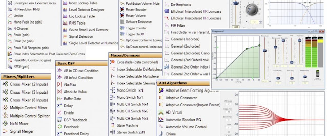
You will need the following blocks for your project in SigmaStudio:
- Input from the IO ToolBox
- DC Blocking from the Filters ToolBox
- Mono Switch Nx1 from the Muxes/Demuxes ToolBox
- Single Level Detector w Numerical Display from the Level Detectors/Lookup Tables ToolBox
Hook them up like this:

Link, Compile and Download to the DSP. Hookup your source to the DSP and start playback. Check the level meter (don't forget to activate it with the GUI switch), it should read less than 0 dB. What if it reads 0 dB? You then have to attenuate it until it reads 0 dB or less. If your source got a volume control, use it to attenuate the signal. If it doesn't have a volume control, use a voltage divider (e.g. a potentiometer or a pair of resistors connected as a voltage divider). You want the input signal to be as close as possible to 0 dB to take full advantage of the 24 bits available on the input but you want some headroom to prevent clipping. How much headroom? If I feed a 1 kHz sine tone through my DAC and measure 1.0 true Vrms on the output. I then read -3 dB on the level detector in SigmaStudio. If I then playback some dynamic music through the same DAC I read around -6 to -8 dB average, with peaks up close to 0 dB on the level detector. So I would recommend an input level of at least -6 dB average on the level detector to be on the safe side (check the peaks with some dynamic music playing). Check each input source and make sure to match the input levels. I prefer to measure and apply required attenuation with voltage dividers for each input source. With the inputs sorted time to take a look at the outputs.
The output level is easier to measure thanks to the built in signal generator. It is generating a 0 dBFS signal so set it to 1 kHz and measure the voltage on the outputs (use a oscilloscope or a multimeter, the latter might measure true RMS but it is more common with average, it is not the same but close enough).
You will need the following blocks for your project in SigmaStudio:
- Sine Tone from the Sources ToolBox
- T Connection from the System ToolBox
- 4x Output from the IO ToolBox
Hook them up like this:
The specification for the output DACs can be found on page 21 in the
ADAU1701 Data Sheet, it reads:
The ADAU1701 includes four Σ-Δ DACs. The SNR of the DAC is 104 dB, and the THD + N is −90 dB. A full-scale output on the DACs is 0.9 V rms (2.5 V p-p).
So 0.0 dBFS out of the DSP core equals 0.9 Vrms on the analog outputs. This might be bad news if the DSP is feeding a power amp with higher sensitivity than 0.9 Vrms. Luckily, this signal is amplified and even turned into differential on the
DSP from 3e Audio. I measured 1.533 (true) Vrms single ended and 3.075 (true) Vrms differential output with a 1.0 Vrms signal @ 1 kHz on the inputs. It equals an overall voltage gain through the DSP of 3.71 dB single ended and 9.76 dB for the differential output. Note that this DSP does not have unity gain. Make sure the output level is matched to the input sensitivity of the power amps.
With inputs and outputs sorted, lets take a look at the DSP core. We already know that anything above 0.0 dBFS will clip on its way out of the DSP. We also know that the headroom in the core is 24 dB. So we need to make sure we never amplify the signal more than 24 dB (e.g. as part of a filter like a Linkwitz transform or by a block like Dynamic Bass Boost etc.). One way is to calculate or measure the amplification trough the core and add a volume control block at the end of your signal flow to attenuate the signal down to 0 dBFS or below. Another way is to use a dynamic processor like a limiter or compressor as the last step in your signal flow to make sure the signal stays below 0 dBFS. Note that compressors might not be full range (-90 dB to +24 dB). If in doubt, use a limiter instead.
This post has been a lot about highest possible level of signal before clipping but what about lowest possible level? It’s commonly said that digital audio’s resolution depends on the bit depth of each sample. Each bit doubles the range of amplitudes that can be stored, and a doubling of voltage is about 6 dB, so 16-bit audio is said to have 16 * 6 = 96 dB of resolution. You can also say that we loose one bit of resolution for each 6 dB attenuation in the digital domain. We got max 28 bits in the core and 24 bits in and out of the core. How many bits can we loose before it affects the sound quality? It depends on your preferences but lets make CD audio the reference. It is 16-bit audio so there is a difference of 12 bits to the core and 8 bits in and out of the core. 12 bits equals 72 dB and 8 bits equals 48 dB. Apply 72 dB attenuation to 24 dBFS or 48 dB attenuation to 0 dBFS out of the core and you still got 16 bits or 96 dB of resolution left (CD quality). Is it good enough? I think so but your milage may vary.