Gotta Go Faster, Part 1.
- Sharing the analog frontend with the DSP analog input is far from perfect
- The analog frontend is always a bit noisy
- The analog frontend is only mono
- The FHT got few bins and poor band resolution
- The Arduino is limited when it comes to memory, floating point math and digital sound input
- Serial data to the LED matrix is somewhat of a bottleneck on the Arduino
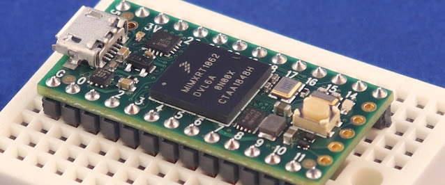
I started to play with the idea of using I2S instead of analog input since I got unused digital outputs on the DSP. My eyes fell on the mighty Teensy 4.0 as an alternative to the Arduino. It comes with a great audio library that is supposed to support I2S. But the library in primarily written for the audio adaptor board so lets start with figuring out how to get I2S audio from the DSP to the Teensy micro controller.
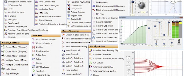
I will lay out the bare minimum in SigmaStudio just as an example. I am using analog input with a DC blocking filter like this:

And a pair of digital outputs for I2S like this:

On the hardware tab make sure you got the following settings:
- Serial output in Master Mode
- Output Word Length 16 bits
- MP6 set to Serial Output Data 0 (this will be left and right channel out)
- MP7 set to Serial Output Data 1 (not used in this example but can be used for another pair of outputs)
- MP10 set to Output Left-Right Clock
- MP11 set to Output Bit-Clock
See red markings below:

This is pretty much the only settings needed and the rest of your SigmaStudie can be anything you like.
Next up is connections to the Teensy. Note that the I2S pinout differ between the Teensy 3 and 4. You find the I2S pins in the yellow section marked Digital Audio on the Teensy 4.0.
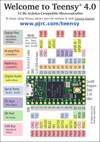
For stereo input from the DSP you have to use the following pins:
- DSP MP6 Serial Output Data 0 -> Teensy 4 Pin 8 (IN1)
- DSP MP10 Left-Right Clock -> Teeny 4 Pin 20 (LRCLK1)
- DSP MP11 Bit-Clock -> Teensy 4 Pin 21 (BCLK1)
Make sure the DSP and Teensy share a common ground and preferably run each pair of cables as twisted pairs with a ground cable. This is all you need and running sound through the DSP should now generate sound on the Teensy I2S input but there are a couple of caveats! First of all, the reason we are running the I2S output from the DSP in master is because the Teensy Audio library is written for 44.1 kHz and the 3e Audio DSP is running at 48 kHz. We therefor have to use the I2S Slave component in the Teensy Audio library in order to let the library run at 48 kHz. This will mess with a lot of components in the library but we will be OK as long as we stay away from the 44.1 kHz dependant components. I am only using the I2S Slave, Mixer, FFT and Peak objects and no other input ot output objects.
NOTE: If you use additional pins for GPIO on an ADAU1701 DSP like the 3e Audio DSP. The 3e Audio DSP documentation state “*Jumper J2&J3 should be ON when setting DSP as the Master(default)”. The documentation is a bit ambiguous in this case.
From the ADAU1701 data-sheet: “If an external ADC is connected as a slave to the ADAU1701, use both the input and output port clocks. The OUTPUT_LRCLK (MP10) and OUTPUT_BCLK (MP11) pins must be set to master mode and connected externally to the INPUT_LRCLK (MP4) and INPUT_BCLK (MP5) pins as well as to the external ADC clock input pins. The data is output from the external ADC into the SigmaDSP on one of the four SDATA_INx pins (MP0 to MP3).”
“Making the external connection” is exactly what the jumpers J2 and J3 do on the 3e Audio DSP. Great if you use I2S inputs but rendering MP4 and MP5 useless if you don't. I have no I2S inputs, I am only using I2S output to the Teensy and I need as many GPIO pins as possible. Keep jumper J2 and J3 installed as long as you need MP4 configured as Input Sdata_in0 and MP5 configured as Input Lrclk_in. Remove the jumpers and configure MP4 and MP5 as additional GPIO pins if you don't need clock information relayed to I2S inputs.
You should now be able to test the I2S connection between the DSP and Teensy with some of the audio library example projects. For example PeakAndRMSMeterStereo.ino. You only need to make changes to the code like remove references to the audio shield and make I2S input in slave mode, like this:
/* Adaptation of Stereo peak meter example, including RMS.
assumes Audio adapter but just uses terminal so no more parts required.

This example code is in the public domain
*/

#include <Audio.h>
#include <Wire.h>
#include <SPI.h>
#include <SD.h>
#include <SerialFlash.h>

AudioInputI2Sslave   audioInput;
AudioAnalyzePeak     peak_L;
AudioAnalyzePeak     peak_R;
AudioAnalyzeRMS      rms_L;
AudioAnalyzeRMS      rms_R;

AudioConnection c1(audioInput, 0, peak_L, 0);
AudioConnection c2(audioInput, 1, peak_R, 0);
AudioConnection c3(audioInput, 0, rms_L, 0);
AudioConnection c4(audioInput, 1, rms_R, 0);

void setup() {
  AudioMemory(6);
  Serial.begin(9600);
}

// for best effect make your terminal/monitor a minimum of 62 chars wide and as high as you can.

elapsedMillis fps;
uint8_t cnt=0;

void loop() {
  if(fps > 24) {
    if (peak_L.available() && peak_R.available() && rms_L.available() && rms_R.available()) {
      fps=0;
      uint8_t leftPeak = peak_L.read() * 30.0;
      uint8_t rightPeak = peak_R.read() * 30.0;
      uint8_t leftRMS = rms_L.read() * 30.0;
      uint8_t rightRMS = rms_R.read() * 30.0;

      for (cnt=0; cnt < 30-leftPeak; cnt++) {
        Serial.print(" ");
      }
      while (cnt++ < 29 && cnt < 30-leftRMS) {
        Serial.print("<");
      }
      while (cnt++ < 30) {
        Serial.print("=");
      }

      Serial.print("||");

      for(cnt=0; cnt < rightRMS; cnt++) {
        Serial.print("=");
      }
      for(; cnt < rightPeak; cnt++) {
        Serial.print(">");
      }
      while(cnt++ < 30) {
        Serial.print(" ");
      }
      Serial.print(AudioProcessorUsage());
      Serial.print("/");
      Serial.print(AudioProcessorUsageMax());
      Serial.println();
    }
  }
}