SigmaStudio Automatic Input Selection

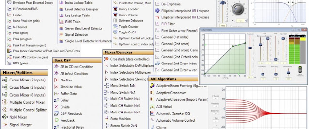
I got a message from a reader of this blog asking about my take on automatic input selection. He was using the 3e Audio DSP just like me and it comes programmed with automatic input selection by default. The only problem is that 3e Audio has hidden the functionality in a locked hierarch board so it is not available to their customers if they want to reprogram the DSP. Why on earth 3e Audio would like to hide this functionality from their customers is beyond me. I have seen statements bout protecting some IP but information about how to put together this kind of functionality is available on the Internet so I really don't get it. Anyway, here is what I put together in SigmaStudio in order to automatically switch between inputs. This example switches between analog and digital inputs. The digital input is prioritised if there is a signal on both and switching between them is done through a cross fade block.

This logic might feel a bit backwards but it works. The Signal Detection block will output a flag as long as no signal is detected on the digital inputs. This will make the Max block output zero in 5.23 format making the Cross Fade block fade fully to analog inputs. The Signal Detection block will stop outputting the flag as soon as a signal is detected on the digital inputs for more than the Trig Time. The flag will go low and the Zero Comparator will output one in 5.23 format. This will make the Max block output one in 5.23 format making the Cross Fade block fade fully to digital inputs. The same concept can be used with multiple inputs using a Multiplexer and 28.0 format instead.