Go Big or Go Home

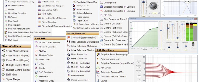
I bought another DSP around Christmas and I had some time to play around with it over the holidays. I got this really interesting idea I wanted to try out so I started to work on a new concept for an integrated. The first question, as usual, what would the faceplate look like? I don't know why but I keep coming back to VU-meters even though I grew tired of my last build with VU-meters within minutes. I used four NISSEI TR-35 for the build but they still didn't manage to make an impression. Was it because they where too small?
I personally find the Technics SE A5 being the king of VU-meters. Those meters are huge and impressive making something like a NISSEI TR-35 look like a tiny toy. Buying a thing like the SE A5 meters seemed impossible so I started to play with the idea of fabricating something like it myself. I kind of hate when I get these kind of ideas, you know - can it be done? Because I just have to find out...
What actually made me take the first steps was the fact that the needles doesn't reach all the way up. Study the picture above and you'll se that they nearly reaches half way up. I guesstimated that I could make my meters something like 40 x 8 cm max, if I wanted to use it on the front panel of my new integrated. I further guesstimated that I would need a needle approximately 55 mm long for it. So I started to look for VU-meters with needles that long. I pretty soon stumbled upon another NISSEI meter, the TN-105. This meter can be had with different faceplates and lighting options. I selected a blue tacky one because I wanted the needles to be black.
This meter comes apart quite easily. It is mostly kept together with some tape. I was not interested it the house or background lighting, just the needle and movement.

The first setback. the movement in TN-105 is not constructed as in the TR-35. It consists of two different parts kept together by the housing. These pieces are magnetic so take it easy while handling them.

So my first task was to copy the shape of the original movement housing and make a 3D print where I could correctly mount the movement. It was fairly easy so I took it as a proof of concept and moved on.

Next step was to design and print a bunch of pieces that would make up the frame. My 3D printer is not wide enough to print 40 cm pieces so I had to make it into a left and a right half. I did not want any ugly seams so I ones again looked at the SE A5 for some inspiration. I figured that a couple of 20 x 10 mm aluminium L-profiles could both hide the seams and add some structure and flair to the frame.
The bottom two pieces to the right was my first attempt of a lighting ramp. I printed it in black since I was too lazy to swap filament. I was also experimenting with some white 5 mm LEDs since I had the laying around. It did not look good so I decided to redesign the top part of the frame entirely...

I printed these parts in PETG because I wanted some extra heat resistance. It is also much easier to machine than PLA. The top piece is untreated and the bottom one has been sanded and polished to a smooth finish. It would have been almost impossible with PLA.

I had struggled with the placement of the power on LED for my integrated. I did not know where to put it? I just knew I did not want it over the power button. I decided to let 10 mm of the aluminium profile show a bit like on the SE A5. I 3D printed a jig and drilled a hole in the profile. I then made a center piece that would fit in between the left and right half of the bottom pieces of the frame. I used a piece of 6 mm acrylic dowel rod to lead and diffuse the status light from a 5 mm LED mounted at the back of the piece.

I had to do this to get an even light on the front given the lack of space from behind. The piece was then sanded and polished before it was fitted between the two other pieces.

The picture below is from my first try to piece everything together. The houses for the meter movement slides into place and washers are used as shims to get the distance between the needle and the frame just right. The meter scale is put on a piece of 2 mm cardboard that mounts from the back. The left and right 3D printed half of the frame are glued to the aluminium L-profiles before everything is screwed together with the two side pieces.

I printed the newly designed lighting ramp in white PETG this time. The top part is a diffusor that is screwed in place over the cables and LEDs. It fits like a lid, as on the bottom piece in the picture.

I dont know why I always construct everything so that it can be taken apart. Probably because I want to be able to alter and repair things. Below are a set of tabs used to keep the cables and LEDs in place.

I used a set of warm white 5050 SMD LEDs this time. They are compact and generate plenty of light.

And this is what it looks like mounted with the diffusors in place. Much better than the black one. Note the tiny hole in the middle of the bottom aluminium profile, it will be the power indicator.

It is hopefully obvious how the frame is constructed and how the pieces come together...

The meter scales mounted from behind and held in place by the frame and some tape. I used Inkscape to draw the scale and printed it on a heavy off-white paper using a regular printer (just enough room for two prints on each side of an A3 sized paper).

And finally everything in place. The 2 mm acrylic glass is kept in place by a special tape (Tesa Powerbond). It looks a bit messy right now but it will not show once mounted to the faceplate. The only thing that will show is the top 10 mm of the bottom aluminium profile, and the meters off course.
Note, no VU label because I am not planning to use these meters as VU-meters. Just a dB scale and a % scale and they are not the same (it is actually one scale on top of another).