The Ultimate Integrate Part 3.

The core of this build is the 3e Audio DSP and TPA3255 two channels class D amplifier. Together with Rod Elliotts P06 RIAA amp and P113 headphone amp. But a couple of auxiliary boards are needed to make this an integrated amplifier.
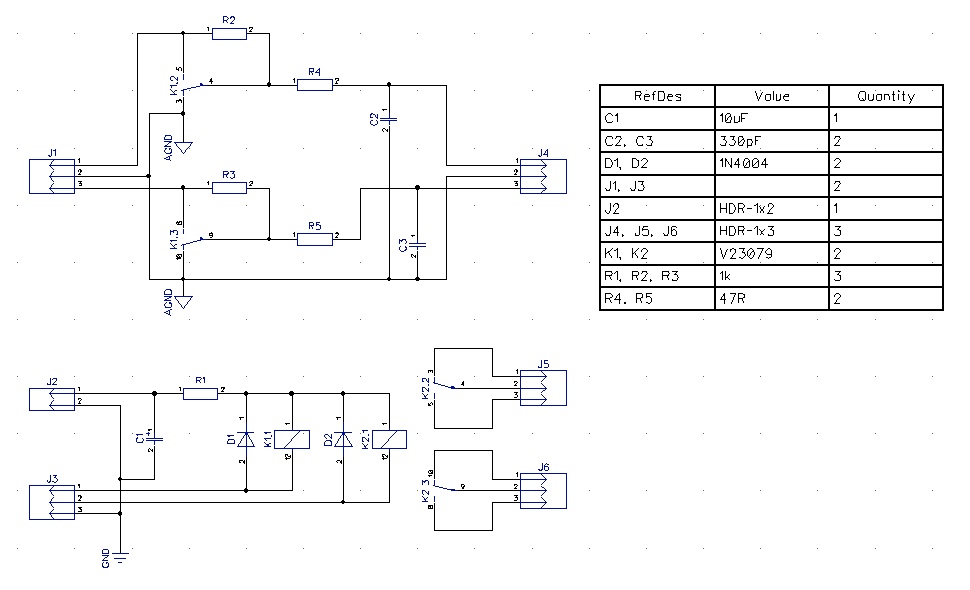
The first problem I had to solve was the input switching. I could have used the board from my PreFUNK. It was built with relays controlled by a rotary switch. This is a simple and efficient solution but it has proven surprisingly hard to find a proper rotary switch. And if you make the labelling on the front panel lets say 36º apart the it rules out all other options like a switch 30º apart. What I wanted instead was something working as a set of radio buttons. Rod Elliotts P163 outlines several options all with their own pros and cons. I wanted something like the CMOS Set-Reset Flip-Flop Switching (Version 2) but fell for another even simpler solution, outlined by crutschow at Electro Tech Online. I got a hunch that it might be a bit too simple relying on the input capacitance of the IC to form a RC-network. I bench tested the circuit on a breadboard and got some key bounce but somehow it didn't stop me from constructing a board around it. I opted to have PCBWay make me a two layer board because I was too lazy to drill all those holes. The boards came out great except for the key bounce issue (this is when you realise that you should have opted for the Rod Elliott circuit because they always work out of the box). The CD4044 got an input capacitance of 0.5 pF. That is a time constant of only 0.0075 ms with a 1M resistor. I ended app adding 10nF capacitors in series with the IC input, after the 1M resistors. It results in approximately 10 ms delay that will take care of most key bounce. You might even go as high as 20 nF for a 20 ms delay. It should take care of even the most extreme key bounce but it will make the button response a bit more sluggish. Best thing is to bench test the circuit with your buttons before deciding on the final value.
The final circuit looks like this. The top part is based on Rod Elliotts P163. It is the relays doing the switching and I added the option of running inputs directly or through a voltage divider. It also drives the indicator LEDs.


This is pretty much whats needed for the audio part but I decided to make a couple of additional boards. A small one acting as small signal star ground, another as a junction board with pull-up resistors for GPIO (distributing 3.3V from Digital I2S Input/output connector (J5) pin 1 and ground pin 2 on the DSP board to all front panel switches). I had already made a Rod Elliott P55 to drive the VU-meters. It is designed for a 50uA or 100uA meter movement and it works great with something like the NISSEI TR-35. But I used a pair of NISSEI TN-105 to make my VU-meters and they are 1000 uA. The parallel resistance between the meter and R8 is supposed to be around 200 Ohms according to Rod Elliott. The TN-105 is 500 Ohms so I went with R8 = 330R. R7 and R9 also has to be adjusted if you want to be able to use the trimmer for input levels between -10 dBV and +4 dBu. I used Tina-TI to simulate the circuit and when with R7/R) = 510R.
The last circuit is a bit gimmicky. Having large backlit VU-meters on the front can be quite distracting in a dark room. So I decided to built a circuit that would just the light level of the VU-meters based on the surrounding light. I figured that PWM would be the way to go with LED light and constructed several circuits based around an LDR and a 555 timer. The component values depend a bit on the LEDs and the LDR so use this circuit as a starting point and adapt it too your needs.

I decided to mount the boards on two different levels since the cabinet is quite high. This is what the bottom level looks like:

Top left board (except power supplies to the far left): +15-0-15V and 12V power distribution and small signal star ground. Bottom left: P55 VU-meter drive board. Top middle: Input switching board. Top right: P06 RIAA amp. Middle right: P113 headphone amp. Bottom middle left: PWM board. Bottom middle: GPIO junction board. Bottom right: muting board.
And this is what the top level looks like:

I made the distance between mounting holes a multiple of 10 mm on all new boards (to fit the pre drilled holes on the inner baseplate). Some boards are already made with other distances so I used the 3D printer to print mounting details and adaptors.