DIY Speaker Measurement Part 5.

You probably have to study hard at the university or at least read some in depth books on the topic to fully understand inner workings of speaker measurement. There are a lot of theories and math involved and my humble blog will not try to cover it all. I will instead try to distill it down to the bare minimum needed for a DIY hobbyist when building speakers and crossovers. I will also present some software tools that will do most of the complex math for you but first some basic concepts and ideas.
We are going to measure sound waves and those waves has a wavelength like in the picture below. Low pitch sound has a longer wavelength than high pitch sound. Over the same period of time there will be less cycles of low pitched sound like bass compared to high pitched sound like treble.

A speaker radiates sound waves and these waves will reflect against any surface. Reflected sound will mix with direct sound making it really hard to tell them apart. When measuring the speaker we want to measure the direct sound and nothing else. Compared to when you do room treatment where you want to measure the room.
The professional solution to measure only the direct sound from a speaker is to use an anechoic chamber. Very few people has access to an anechoic chamber so we will have to find another way of eliminating reflected sound. The measurement method we are going to use for this is called quasi-anechoic or gated-impulse far-field measurements (it is the same). The idea is actually quite simple and I will illustrate it with the following image below.

The measurement microphone is placed 1 meter from the speaker and 1.2 meters above the floor. All other reflective surfaces are assumed to be further away than the floor. Direct sound travels along the green line and the first reflection travels along the red line. The distance along the green line is shorter than the distance along the red line. The difference given the speed of sound represents represents a time window of 4.65 ms between the moment the direct sound hits the microphone until the first reflective sound arrives and start messing things up. Those 4.65 ms are pretty much like having an anechoic chamber and therefor the name quasi-anechoic or gated-impulse far-field measurements since we put a gate around out measurements and only use the short period of direct sound.
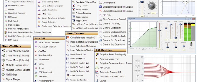
There is however a major drawback with the quasi-anechoic method. The limited time window makes it impossible to capture frequencies above a certain wavelength. The exact threshold is dependent of the distance between microphone, speaker and first reflective surface. It is 215 Hz in the example above. But how do you know all this? Time to introduce a piece of brilliant software generously made available for free by its author Kimmo Saunisto. The software is called VituixCAD and is an application for speaker and crossover simulation. But it also contains additional invaluable tool that can be used when measuring speakers. The picture above is actually a screen shot from the Auxiliary tool in VituixCAD. It contains several tabs with a tool each to make all sorts of calculations. The tab used above was the "Time window" and the screen shot below is from the tab "Wave length".

To summarize things this far. We can use quasi-anechoic measurements from a certain threshold around 200 Hz in an ordinary room with a ceiling height of around 2.4 meters if the DUT is placed in between with at least 1.2 meters distance to any reflective surface. We can also make measurements in a larger room or outside with even greater distance to reflective surfaces in order to lower the minimum frequency even further. How far? Software like VituixCAD can be used to make that kind of math for us.
But what about the frequencies below the threshold? We are going to use another method for them called near-field measurements. The idea is to put the microphone so close to the speaker element that the direct sound will overpower any reflective sound. The major drawback with this method is the opposite to the quasi-anechoic method, it can not be used for frequencies over a certain threshold. The threshold is based on the size of the speaker element and we can use the "Near field" tab on the VituixCAD Auxiliary tool to make the math for us. In the example below I used 305 mm (around 12 inch) for the diameter of the element. It would make it possible to use near field measurement up to 359 Hz with the microphone no further away from the element than 16.8 mm.

But what about ports and passive radiators? There is a good chance that they are used with frequencies below the threshold for the quasi-anechoic method so we measure them with the near field method. A passive radiator like a regular speaker and a port with the microphone in the center of the port, flush with the baffle.
Multiple measurements from different angles or from bass elements and ports etc. needs to be merged together to get the speakers total response. The math involved is quite complex and near filed measurements of elements and ports of different size needs to be scaled to each other. We will once again use a tool from VituixCAD to do the heavy lifting for us. Enter the Merger tool as seen in the picture below.

The top part contains near filed measurement of element and port. The scaling factors has been calculated by the Merger tool based on area of element and diameter of port. The lower part contains gated-impulse far-field measurements from different angles. Far filed and near filed measurements still need some additional tweaking to be spliced together at a suitable level and frequency and the option to include baffle-step diffraction response has not been used in this example. The reader is therefor urged to read the VituixCAD User Manual, not only about the Merger tool but also about VituixCAD itself and all other tools it contains. Also read the document VituixCAD Measurement Preparations for a great checklist and guide to speaker measurement preparations.
To summarize this post:
- Quasi-anechoic also called gated-impulse far-field measurements can be used to measure the upper frequency spectrum from around 200 Hz depending on distance to the nearest reflective surface.
- Near-field measurements can be used to measure the lower frequency spectrum from 20 Hz up to around 400 Hz depending on the size of the radiating element. It can also be used to meassure ports and passive radiators.
- A tool like VituixCAD Merger can be used to scale and splice far field measurements with near filed measurements to get the speakers total response.